
I’ve been having some powerful dreams of building a custom bicycle for bicycle touring adventures such as I’ve enjoyed a few times before— but this time, I want to incorporate a few really novel elements into the design, so that the resulting vehicle can effectively meet the serious(!) challenges (and experience the opportunities) of both the all-terrain amphibious Kinetic Sculpture Race (KSR), and the at-times brutal Race to Alaska – a 750 mile coastal boat race up the entire length of British Columbia, in the wild Pacific ocean, with one rule: no motors. So: what I’ll build will not look exactly like a typical bicycle, but it will function like one- as well as a (fast? fast.) and seaworthy small sailboat.

Whatever I build will need to be able to traverse steep and soft sand-dunes, rocky river shores, roll along miles-long coastal beaches, pedal easily over 50+ miles of paved roads, or, in the Race to Alaska, weather incredibly challenging conditions including steep waves and at times gale-force winds in the north Pacific. (Several boats in the 2019 R2AK snapped centerboards off, and broke rudders, due to the violence of the conditions encountered at the start of the epic 2019 R2AK).

Can I design, fabricate, and pilot a very-seaworthy bicycle/watercraft through all these conditions? I think so, and I’ll share here my progress towards this objective.
COVID IMPACTING GCKSR and R2AK
Unfortunately, because of the pandemic, both of my best motivating deadlines, the Kinetic Sculpture Race and the Race to Alaska, have been called off due to concerns of contagion and the closed international borders with Canada, respectively. But, there is an online group of weird bicycle-building creative souls, called “FreakBikers Unite!“, which is conveniently having a build-a-thon, internationally via the internet, and so this will be the framing and helpful-deadline to keep this project motivated. (To be honest my goals are beyond any of these events, but they each provide unique framing and motivation). The rules of the so called “LOLBO” or “Laugh out Loud Build Off”, are that it must be Rideable, and it must make people laugh. (No mention of Amphibious there, but it’s not ruled out, certainly). (More on why this will make people laugh, and what art it is/carries during the Kinetic Sculpture Race, later.)
The remainder of these posts will be at times highly technical, as I need to teach myself (I get to teach myself) a lot of new skills to pull off what I have in mind- but I’ll try to come up for air from time to time and put all the technicalities into context, if you bear with me. Skills like working with composite materials (fiberglass, carbon fiber) and figuring out the boat-builder tricks of how to efficiently work with the curvy shapes that water flows most kindly over. (As a rule, boats are nowhere flat or square, and so designing and building them takes some real out-of-the-box thinking compared to most other branch of engineering). Molding, in particular, is going to be something I’ll get much more familiar with over this project.
CHALLENGE #1
MEASURE THE DONOR KAYAK:
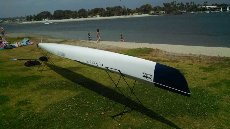
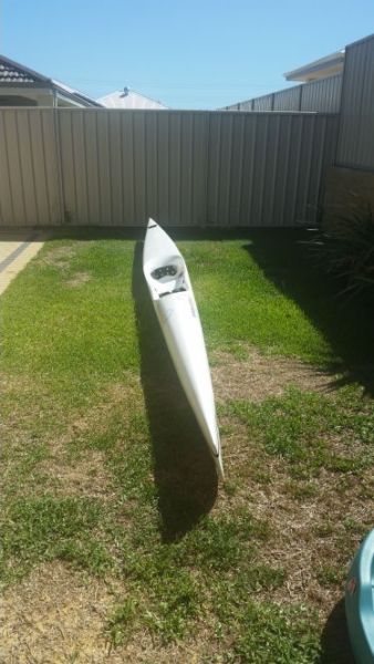
I’m going to be building upon a donor kayak, thus saving myself incalculable hours sanding and fairing. The donor kayak I found is pretty spiffy, too- a Fenn “Millenium”. At 21′ long and only 17″ at it’s widest, and with a wave-piercing axe bow, it’s quite easy on the eyes, and the water. (A friend who used to professionally race sea kayaks said it was among the fastest kayaks in the world). The length-to-beam ratio is 14(!): just slightly broader than a needle in the water. And the thing is incredibly light – it’s built of carbon fiber, and weighs maybe 35 pounds, all 21 feet of it. It won’t stay that weight for long, as I repair and add to it, but it’s a good start.
Before you go assume I’m either Mr. Moneybags (I think these things sell new for on the order of $2k) or Mr. Incredibly Wasteful (ie. how dare he cut into a perfectly good kayak!), let me mention that I saved this kayak from the trash heap; It blew off a vehicle and has two big cracks, like beltlines, running around the hull. Its previous owner was happy to drive it to me in exchange for gas money and a steak lunch.
Before I describe what I’m going to add to it, and how, and why, I need to measure what I have already:
STEP 1: 3D SCAN THE HULL
(STEP 1.1: BUILD A 3D SCANNER)
Given that I want to leverage digital fabrication techniques like CAD, CAM, and CNC tools like 3d printing and CNC milling/routing, I really need accurate geometry for what I’m starting with. Also, since repairing the hull will require me to cut the top off the kayak, there’s a risk it could fall out of shape, since it’ll then be quite flexible. So I need to make an accurate cradle to support the hull while it’s weakened. To make this cradle, as well as model accurate additions to the hull (which I’ll get into later), I need to measure the shape of the hull very accurately. But boats are nowhere flat or square, so how do you measure the 3D shape of a boat to make an intimately fitting cradle for it along it’s whole length? For starters, having a support every foot or so along the length will be sufficient. I only need to make 20 or so frames to cradle the hull in cross section, every foot or so. There’s many ways this could be done (“ticking stick” template making, or bending a lead bar around it which is then removed and traced, were two considered options) but I ultimately decided to leverage my extensive collection of robotics gizmos like linear slides, bearings and shafts, and highly accurate angle-encoders.
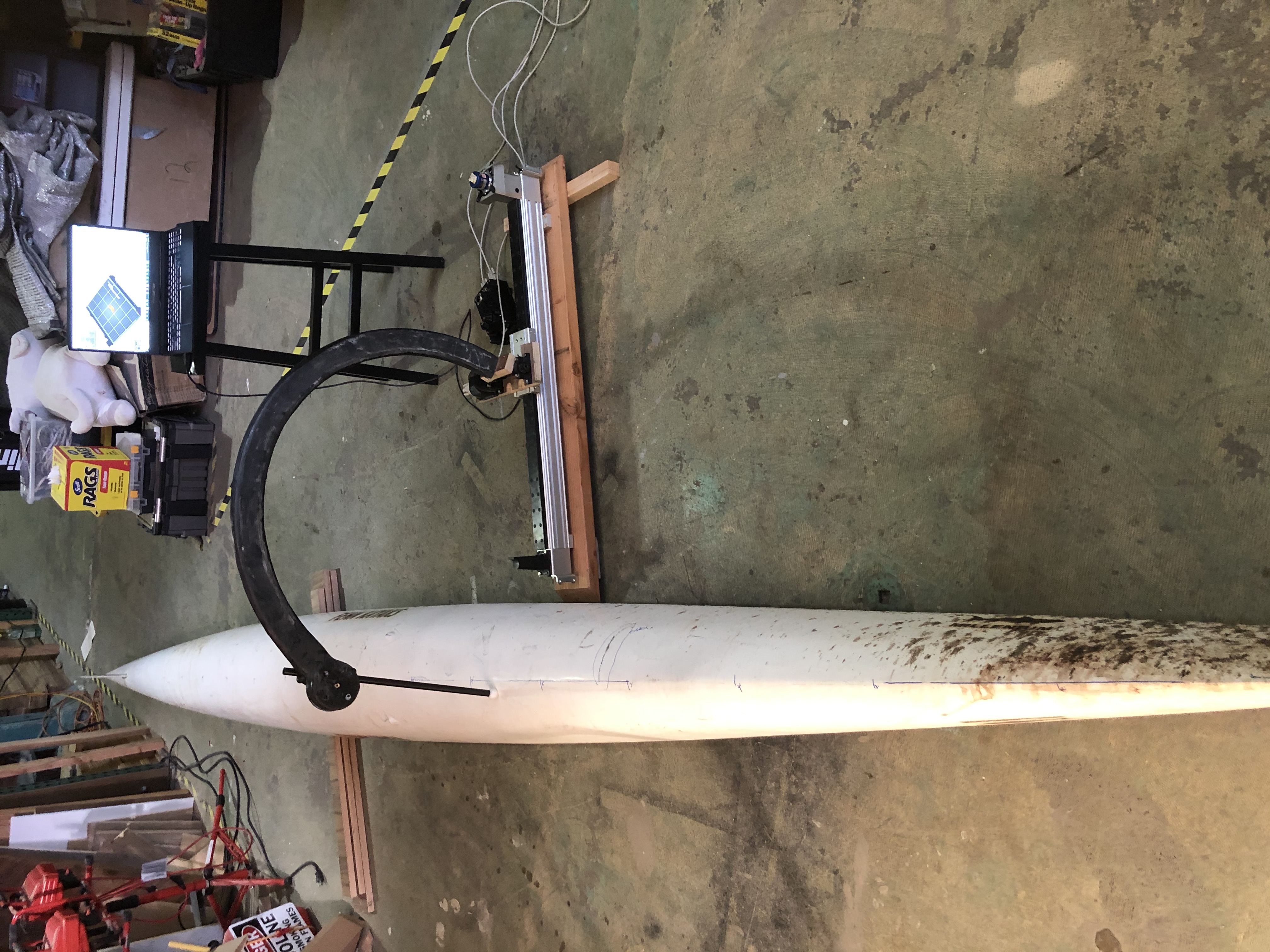
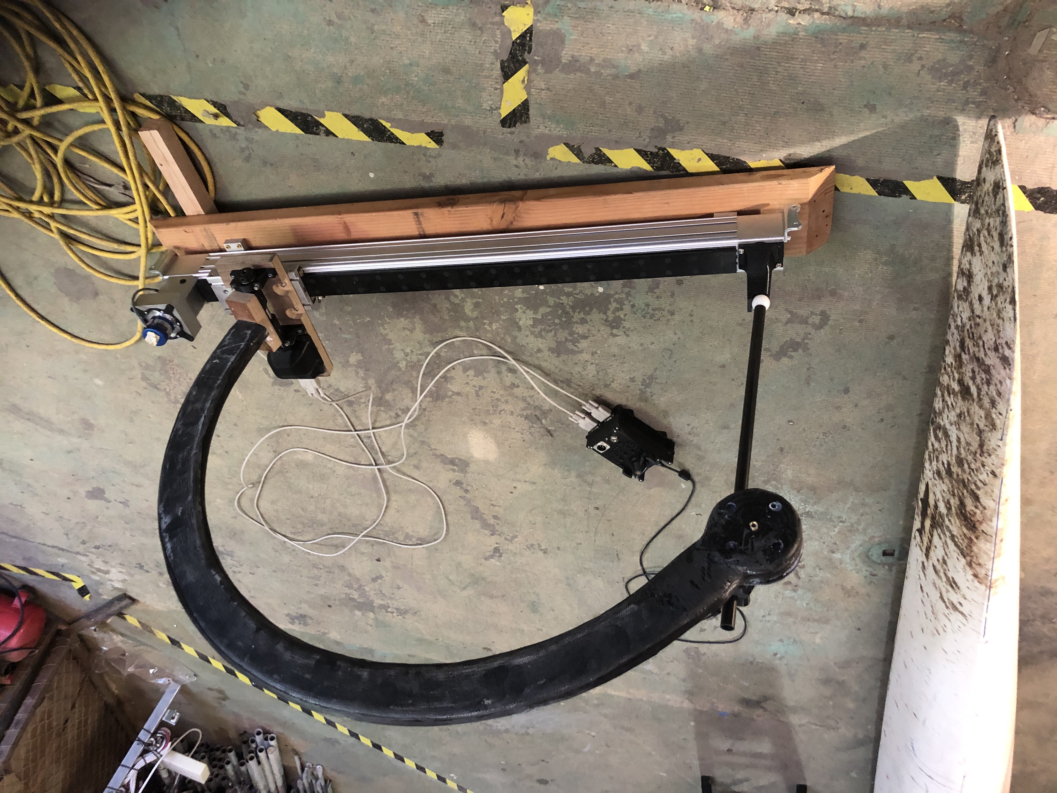
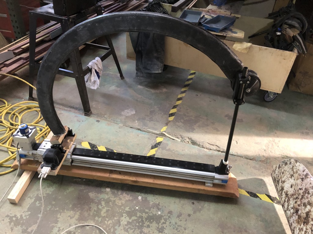
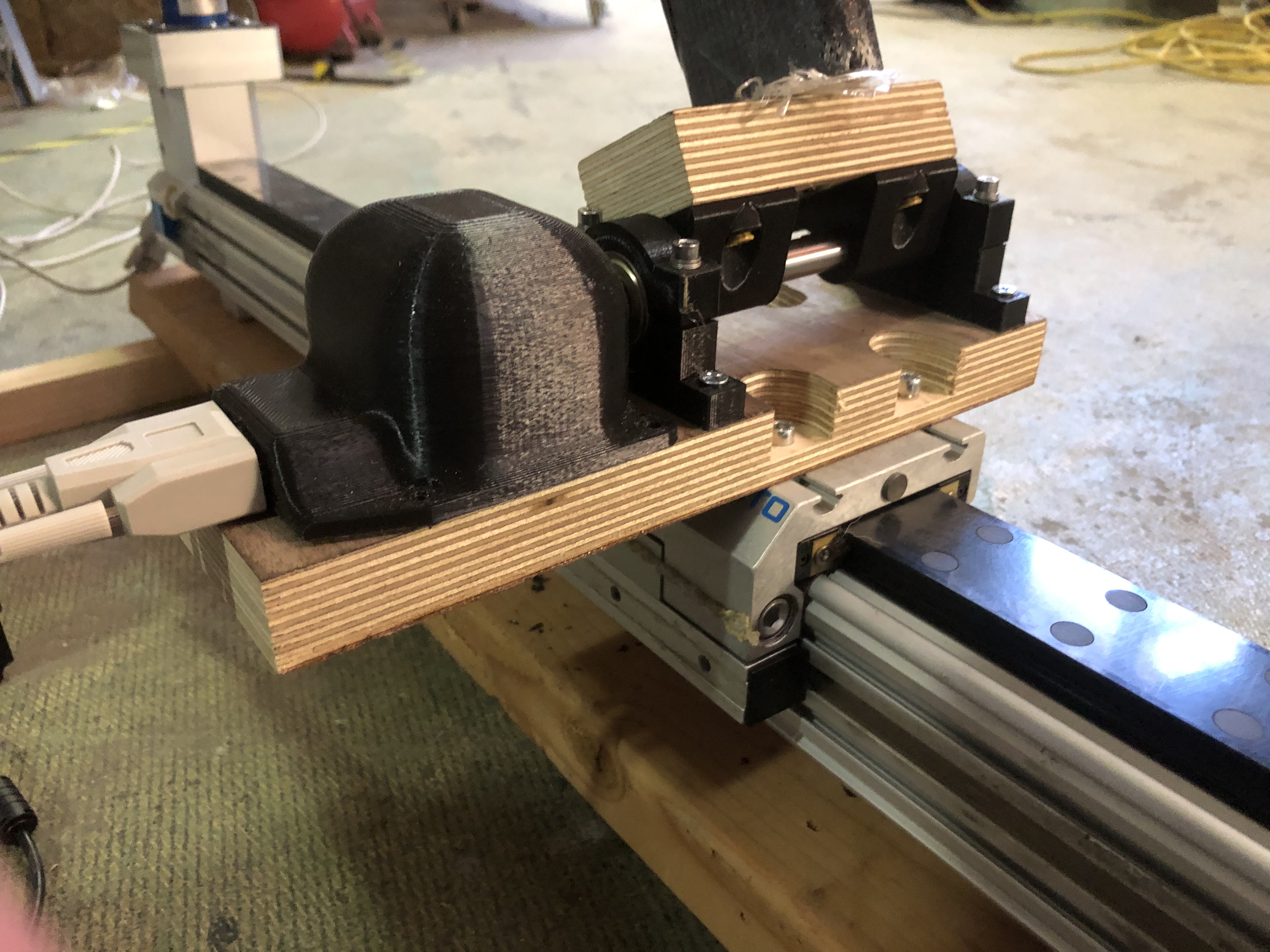
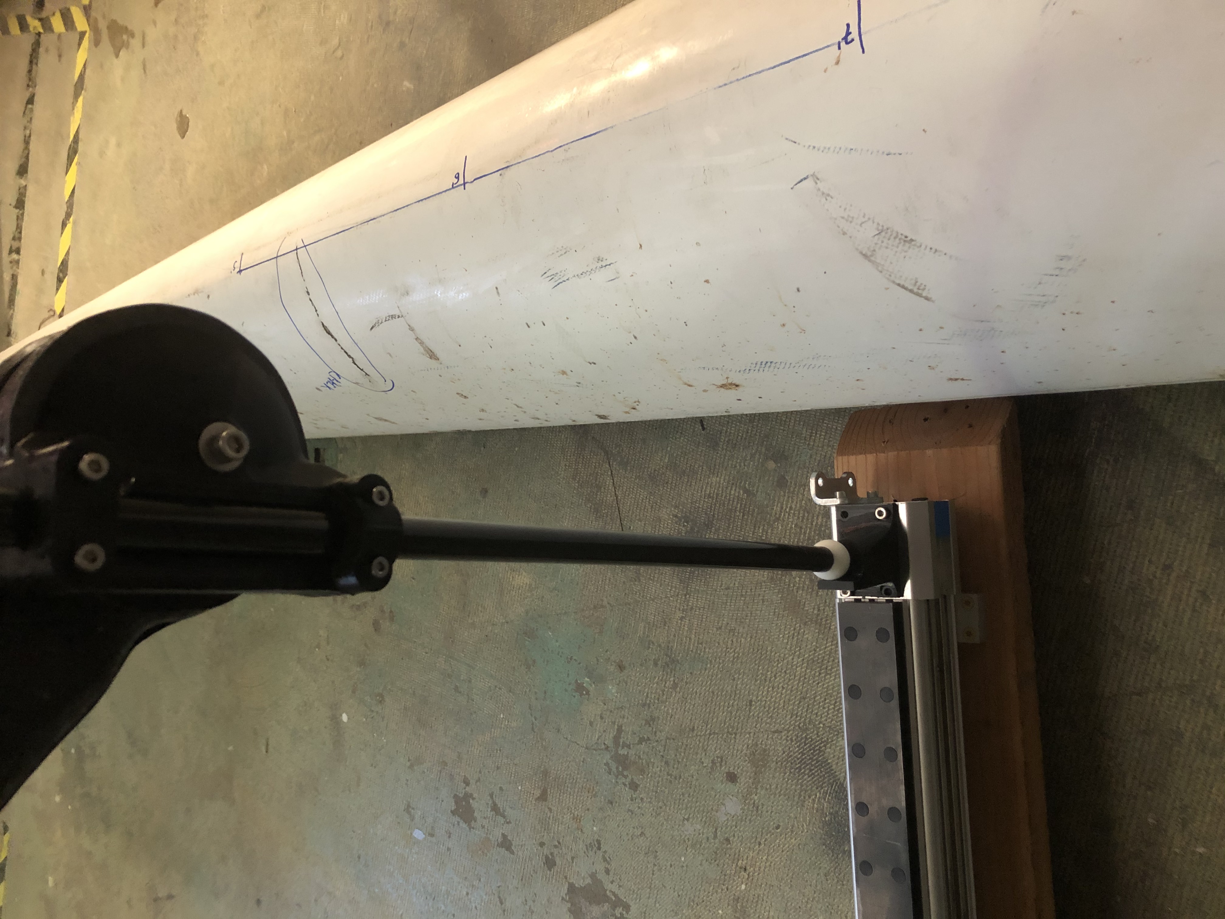
Anyway… today (4/2/21) I got it all working and now I have a gizmo that can scan curvy boat hulls very accurately, allowing me to make parts that fit and extend the hull very smoothly. Hooray! Hull Scans will be updated tomorrow:-)
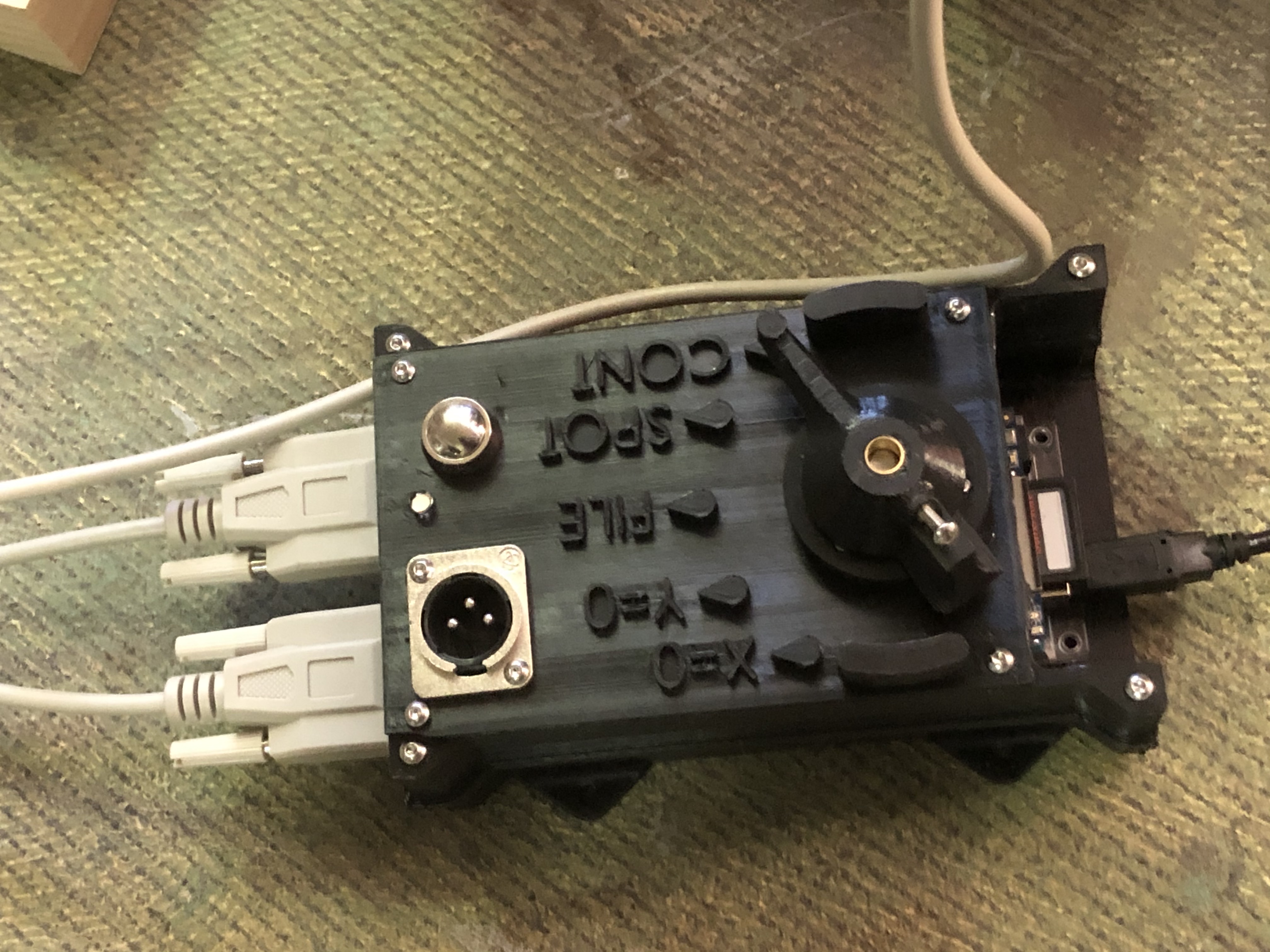
Source Code for the Data Logger Touch Probe:
/* Two-Encoder Data Logger for Measuring Hull Shape
* Gordon Kirkwood March-April 2021
* based on two-encoder reader example code, and SD library data logger source code
42 black LED+
40 white LED-
38 gray button sw
36 purple button sw
34 blue COMMON return of selector switch- ground it
32 green continuous record mode- (?while button pressed, or until pressed again? At ~10hz or every 5mm pathlength from last point?)
30 yellow spot record mode – record a datapoint upon each button press (rising edge)
28 orange “file” mode- button press initiates a new file. Press between each segment.
26 red “Y=0” calibration zero – button press sets Y value to zero (do this while ball on stand)
24 brown “X=0” calibration zero – button press sets X value to zero (do this while ball on stand)
18,19- X channel encoder's quadrature inputs
20,21- Y channel encoder's quadrature inputs
*/
//included libraries
//NOTE: The most recent SD card library does NOT work with my older SD shield on the mega, I had to hunt around, find the older library,
//uninstall (move out of the libraries folder) the default (current) SD library, and install the older version before it would recognize my SD shield
//link to the older SD shield library and explanation: https://learn.adafruit.com/adafruit-data-logger-shield/for-the-mega-and-leonardo
#include <Encoder.h>
#include <SPI.h>
#include <SD.h>
//values used for the return of modes from the identify_mode() function
#define MODE_CAL_X 1
#define MODE_CAL_Y 2
#define MODE_FILE 3
#define MODE_SPOT 4
#define MODE_CONT 5
#define MODE_UNKNOWN 0
//define the two input encoders on the scanner
Encoder knobX(18, 19); //on the arduino mega, pins 2,3,18,19,20,21 are able to external-interrupt, giving fastest response to encoders.
Encoder knobY(20, 21);
const int chipSelect = 10; //setup for SD shield
unsigned long time; //for tracking how frequently to output coordinates, when time-limiting the output rate
unsigned long nexttime; //this value is set when a value is output, as the soonest the next output should occur\
//these values store millisecond counts
unsigned long save_every_X_ms = 1000; //time interval at which position is logged to datafile, if limited free-running sampling mode (not used)
//in milliseconds, presuming one or more values has changed since the last logged coordinates.
//if values haven't changed since last last logged coordinates, no new value is recorded.
//FOR FUTURE MOD: compute the approximate distance traveled since last data coordinates,
//and attempt to log datapoints at semiuniform intervals of spatial coordinates, possibly with
//allowance for corners and where there are sharp changes in coordinates, where values might be recorded
//at finer spatial increments.
//otherwise I will perform this resampling in matlab or similar postprocessing software.
File dataFile; //sd card data structure
char filename[16]; //string to read in and manipulate filenames in
/* pins for mode selector (grayhill multipole switch) user input knob, and the wire colors connected to them, are included in the following pinout table
* MEGA PIN wire color function
42 black LED+
40 white LED-
38 gray button switch
36 purple button switch (short the two leads to trigger spot recording, or select various options.
34 blue COMMON return of selector switch- ground it
32 green continuous record mode- (?while button pressed, or until pressed again? At ~10hz or every 5mm pathlength from last point?)
30 yellow spot record mode – record a datapoint upon each button press (rising edge)
28 orange “file” mode- button press initiates a new file. Press between each segment.
26 red “Y=0” calibration zero – button press sets Y value to zero (do this while ball on stand)
24 brown “X=0” calibration zero – button press sets X value to zero (do this while ball on stand)
*/
int LED_HIGH_PIN =42;
int LED_LOW_PIN =40;
int BUTTON_PULL_PIN =38; //write low on this
int BUTTON_READ_PIN =36; //input_pullup on this - when connected by bytton to BUTTON_PULL_PIN it will be pulled down
int MODE_RETURN_PIN = 34; //set to low, then set input mode pins to input pullup, mode pins are active when grounded
int MODE_CAL_X_PIN = 24; //grounded to MODE_RETURN_PIN if CAL_X mode selected
int MODE_CAL_Y_PIN = 26; //grounded to MODE_CAL_X_PIN if CAL_Y mode selected
int MODE_FILE_PIN = 28; //etc...
int MODE_SPOT_PIN = 30;
int MODE_CONT_PIN = 32;
long inter_blink_interval = 200;
long blink_duration = 50;
//main loop variables
long newX, newY; //to tell if values are changed, I compare new values and old values at each update.
long x = 0; //initialize local variables for both enncoders, here called x and y (channel). note that the encoder datastructure maintains a separate internal private variable for position, so
//to calibrate or zero values requires encoder.write(val); to be called, not just setting these values to zero.
long y = 0;
long min_delta_Y = 10; //minimum increment of Y encoder between recorded datapoints - the larger this value, the less frequently datapoints will be written
long min_delta_X = 10; //minimum increment of X encoder between recorded datapoints.
int mode = 0; //use mode definitions in header for various operating modes
int last_mode = 0; //track if mode has changed
int button = 1; //button status. input pullup defaults to 1 in case of no buttonpress.
int last_button = 1; //track if button changed from last evaluation. initialize to 1 because default (without button press) is input_pullup, so defaults high.
//************************************************************************************
void beep_LED(){ //turns on LED for 100ms.
digitalWrite(LED_HIGH_PIN,HIGH);
digitalWrite(LED_LOW_PIN,LOW);
delay(100);
digitalWrite(LED_HIGH_PIN,LOW);
}
//************************************************************************************
void increment_filename()
//this function searches for files with a name matching a certain pattern, incrementing a counter variable present in the filename until it encounters a name which doesn't exist\\
//note: if files are removed from the directory, so that there is not a full sequence of files prefix000, prefix001, etc... up to prefixNNN, this code will fill those gaps, resulting in nonlinear sequence of files.
{
long lastblink=0,nextblink = 0;
lastblink = millis();
nextblink = lastblink + inter_blink_interval;
if (dataFile) {//close file if it is open, because we'll be creating a new file.
Serial.println("closing previously open datafile.");
dataFile.close();
Serial.print("echoing contents of previous file:");
Serial.println(filename);
Serial.println("****************************************** begin echoing file>>");
dataFile = SD.open(filename);
while (dataFile.available()) {
Serial.write(dataFile.read());
if (millis() > nextblink) //blink LED while data file being echoed over serial port, so that you know that device is not yet ready to record new data.
{
beep_LED();
nextblink = millis() + inter_blink_interval;
}
}
Serial.println();
Serial.println("****************************************** Done echoing file.");
}//if datafile exists
else
{
Serial.println("datafile was not open");
}
//below code finds initial file name to begin with (may be repeated in main loop if button pressed while in "file" mode, to increment filename.
int n = 0; //terating variable for file numbers in names with a consistent pattern
// initialize filename in the consistent pattern chosen
snprintf(filename, sizeof(filename), "data%03d.txt", n); // includes a three-digit sequence number in the file name
//search for filenames in given pattern until the name DOESNT exist- thats the next file.
while (SD.exists(filename)) {
n++;
snprintf(filename, sizeof(filename), "crv%03d.txt", n);
}
//now filename[] contains the name of a file that doesn't exist
//to open file for writing eg in main loop:
Serial.print("opening file: ");
Serial.println(filename);
dataFile = SD.open(filename, FILE_WRITE); //THERE WAS MY PROBLEM: I HAD variable type before dataFile (ie. File dataFile), which compiler understood to define a LOCAL variable, overriding / taking precedence over global dataFile variable.
if (dataFile) { //if file was opened OK
// Serial.println(n);//number of file
Serial.println("Successfully opened file.");
//do not close file; it must remain open to accept data written.
dataFile.println(filename); //for testing purposes write the file's name into the file itself as a header.
//dataFile.close();
}
else {//error opening file
Serial.println("error opening file");
while (1); // end execution.
}
}
//************************************************************************************
void setup() {
Serial.begin(9600);
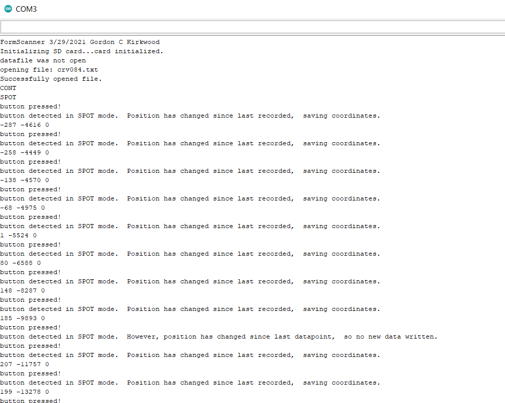
Serial.println("FormScanner 3/29/2021 Gordon C Kirkwood");
//now setup the data card
Serial.print("Initializing SD card...");
pinMode(SS, OUTPUT);
//setup LED as output
pinMode(LED_HIGH_PIN,OUTPUT); //LED high pin
pinMode(LED_LOW_PIN,OUTPUT); //LED low pin
//blink LED once to indicate circuit coming alive.
digitalWrite(LED_HIGH_PIN,HIGH); //this pin will toggle to turn LED on and off
digitalWrite(LED_LOW_PIN,LOW); //this pin will remain low
delay(100);
digitalWrite(LED_HIGH_PIN,LOW);
//button press detection
pinMode(BUTTON_PULL_PIN,OUTPUT); //button pulldown
digitalWrite(BUTTON_PULL_PIN,LOW); //leave this pin low; it will short out the weakly-pulled-high button_read_pin input.
pinMode(BUTTON_READ_PIN,INPUT_PULLUP); //button read, active low (button press causes button_read_pin to go low.
//setup mode selector knob
pinMode(MODE_RETURN_PIN, OUTPUT);
digitalWrite(MODE_RETURN_PIN, LOW); //pull low
pinMode(MODE_CAL_X_PIN,INPUT_PULLUP); //grounded to MODE_RETURN_PIN if CAL_X mode selected
pinMode(MODE_CAL_Y_PIN,INPUT_PULLUP); //grounded to MODE_CAL_X_PIN if CAL_Y mode selected
pinMode(MODE_FILE_PIN,INPUT_PULLUP); //etc...
pinMode(MODE_SPOT_PIN,INPUT_PULLUP);
pinMode(MODE_CONT_PIN,INPUT_PULLUP);
// see if the card is present and can be initialized:
if (!SD.begin(10, 11, 12, 13)) { //these are the pins for connection to older adafruid arduino SD shield; not same for current generation of boards.
Serial.println("Card failed, or not present, halting.");
// don't do anything more:
while (1) ;
}
Serial.println("card initialized.");
//timer initialization for write-every-so-on timing
time = millis();
nexttime = time;
increment_filename(); //find a filename that is new, and open it.
knobX.write(0);
knobY.write(0); //ensure both encoders start with a default zero value.
} //setup ends with a data file opened, a file structure variable named "dataFile", and a character array "filename[]" containint it's name.
//in the subsequent loop, it may be necessary to find a "next file name", by closing the existing file.
// \code to open and test file. ****
//************************************************************************************
void echo_mode(int m) //for debugging over serial port, echo what the mode select switch is
{
switch (m) {
case MODE_CAL_X:
Serial.println("CAL_X");
break;
case MODE_CAL_Y:
Serial.println("CAL_Y");
break;
case MODE_FILE:
Serial.println("FILE");
break;
case MODE_SPOT:
Serial.println("SPOT");
break;
case MODE_CONT:
Serial.println("CONT");
break;
default:
Serial.println("mode unknown");
break;
}//switch
}
//************************************************************************************
int read_mode() {
//function identify_mode() reads the mode pins by setting the common pin low, and all the poles of the selector go to input_pullup pins. Returns an integer MODE code, as defined in header, signifying which mode.
/* pins for mode selector knob are included in the following pinout table
* MEGA PIN wire color function
42 black LED+
40 white LED-
38 gray button sw
36 purple button sw
34 blue COMMON return of selector switch- ground it
32 green continuous record mode- (?while button pressed, or until pressed again? At ~10hz or every 5mm pathlength from last point?)
30 yellow spot record mode – record a datapoint upon each button press (rising edge)
28 orange “file” mode- button press initiates a new file. Press between each segment.
26 red “Y=0” calibration zero – button press sets Y value to zero (do this while ball on stand)
24 brown “X=0” calibration zero – button press sets X value to zero (do this while ball on stand)
*/
digitalWrite(MODE_RETURN_PIN,LOW); //make sure the mode_return_pin is able to pull any selector contact low
if (0==digitalRead(MODE_CAL_X_PIN)){return MODE_CAL_X;}
if (0==digitalRead(MODE_CAL_Y_PIN)){return MODE_CAL_Y;}
if (0==digitalRead(MODE_FILE_PIN)){return MODE_FILE;}
if (0==digitalRead(MODE_CONT_PIN)){return MODE_CONT;}
if (0==digitalRead(MODE_SPOT_PIN)){return MODE_SPOT;}
return MODE_UNKNOWN;
}
//************************************************************************************
int read_button(){
//I need to modify so I only detect rising edges, and debounce button. for now, debouncing in the calling-code, with a short delay.
digitalWrite(BUTTON_PULL_PIN, 0);
return(digitalRead(BUTTON_READ_PIN));
}
//************************************************************************************
void save_values(long thisx, long thisy, long thisz){
//writes an XYZ triplet to the already open datafile.
//assumes that datafile is already open for writing to.
// make a string for assembling the data to log:
String dataString = "";
// read encoder values and put into a string to write to file
dataString += String(newX);
dataString += " ";
dataString += String(newY);
dataString += " ";
dataString += String(0); //solidworks wants triplets, ie XYZ values, so write a constant 0 at the end of each row. (Z placeholder)
dataFile.println(dataString); //************
//dataFile.flush(); //************
Serial.println(dataString);
}
//************************************************************************************
void loop() {
newX = knobX.read();
newY = knobY.read();
//x and y record the last values of these, and are only updated to the newX and newY values upon a data-save event, so that I don't record duplicate values in the file.
mode = read_mode();
while (mode == MODE_UNKNOWN) mode = read_mode(); //wait until the value settles when switching between settings;
//because the switch breaks contact first, then makes next contact ("break before make") so transitions are noisy
//update mode display only when the mode changes
if (last_mode != mode){
echo_mode(mode);
last_mode = mode;
}
//echo if rising edge on button press
button = read_button();
if (button && !last_button) //rising edge
{
Serial.println("button pressed!");
delay(100); //crude debounce, but effective since data collection rate is slow.
//insert code here to handle various modes.
switch (mode) {
case MODE_CAL_X:
Serial.println("button detected in CAL_X mode, setting X-> 0");
knobX.write(0);
break;
case MODE_CAL_Y:
Serial.println("button detected in CAL_Y mode, setting X-> 0");
knobY.write(0);
break;
case MODE_FILE:
Serial.println("button detected in FILE mode, starting a new file.");
increment_filename();
break;
case MODE_SPOT:
//write a line of text to the file
//newX and newY were already read at the start of the loop, no need to re-read them.
//check if (position has changed on either encoder since x and y were last written to the file (and newx value propaged to stored X, and newY propaged to stored Y)
if ((x != newX) || (y != newY)) //only save values if different from before.
{
Serial.println("button detected in SPOT mode. Position has changed since last recorded, saving coordinates.");
x = newX; //update position trackers so the "value changed" test above can detect subsequent changes.
y = newY;
save_values(x,y,0);
}
else
{
Serial.println("button detected in SPOT mode. However, position has changed since last datapoint, so no new data written.");
}
break;
case MODE_CONT:
Serial.println("button detected in CONTINUOUS mode. However, button has no effect in continuous mode. Data is recording by default");
break;
}//switch
}//if button pressed
last_button = button;
if (mode==MODE_CONT)
//continuous data logging means no button press required to trigger it.
//plan: check if X or Y encoder has changed by at least min_X_increment or min_Y_increment. if either encoder has changed by at least this much, then record the datapoint to the file.
//also record to file regardless of change in X or Y since last recorded, if the mode has JUST changed to MODE_CONT.
if (((abs(x-newX) >= min_delta_X) || (abs(y-newY) >= min_delta_Y)) || (last_mode!= MODE_CONT)){
x = newX;
y = newY;
save_values(x,y,0);
Serial.println("CONT mode, motion detected, datapoint written.");
}
}//loop