I needed a lightweight, impact resistant, streamlined fairing for a flying robot. I could 3d print a part with the right shape, but 3d printed materials would either be too weak, or too heavy. I’ve been considering a hybrid workflow which this was the perfect opportunity to try out: 3d printing a mold for composite layup.
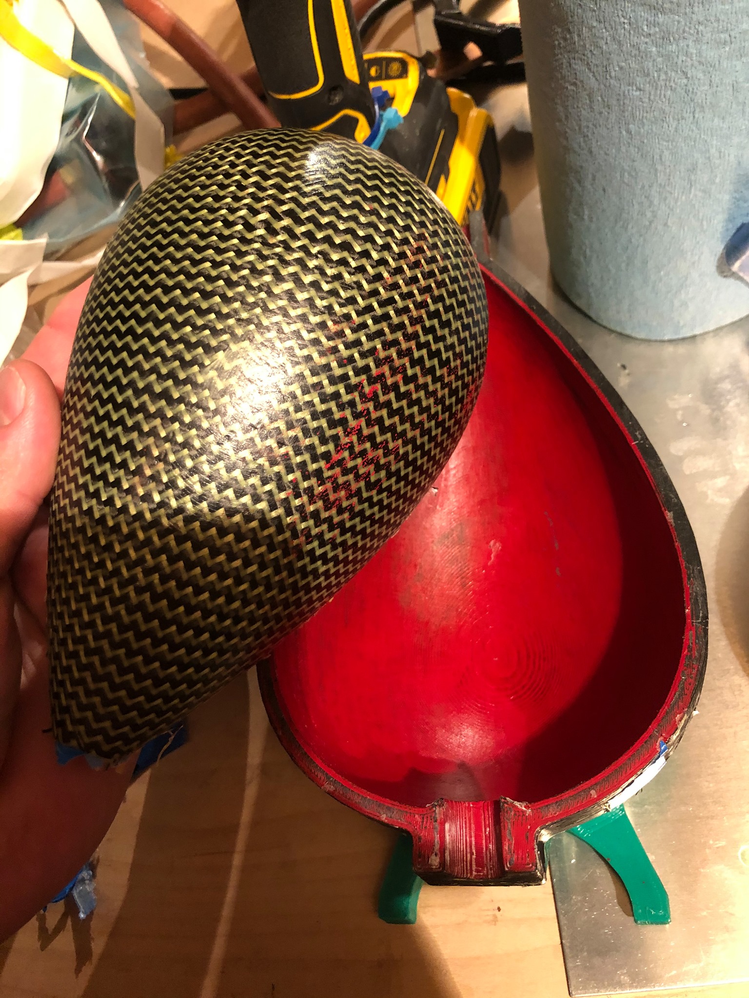
Carbon Kevlar Nacelle half made in a 3d printed mold. The shape is a solid of revolution using a scaled NACA airfoil shape that has 33% chord-to-length ratio, about 8″ long. The only fault is that some of the mold-filling red paint transferred to the part – a purely cosmetic issue.
It worked wonderfully! The mold printed overnight, and after some sanding primer was applied and sanded down to a 600 grit finish, I waxed the mold, and it was ready to invest with fabric. I vacuum bagged the parts for good consolidation, and am very pleased with the results, shown above.
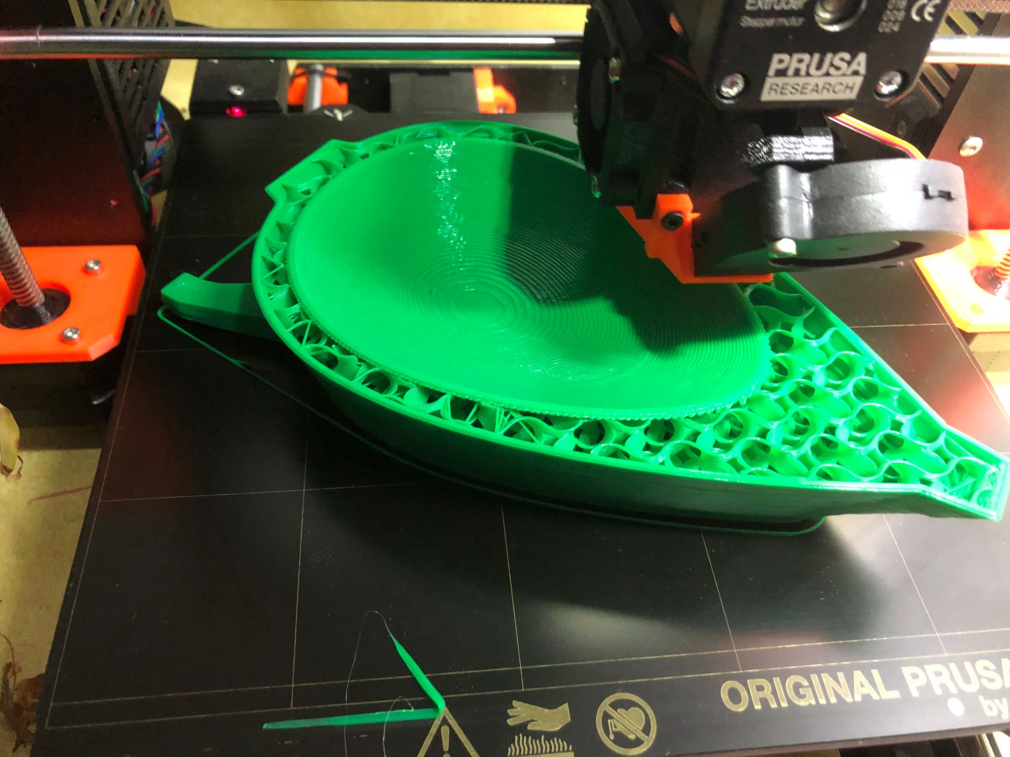
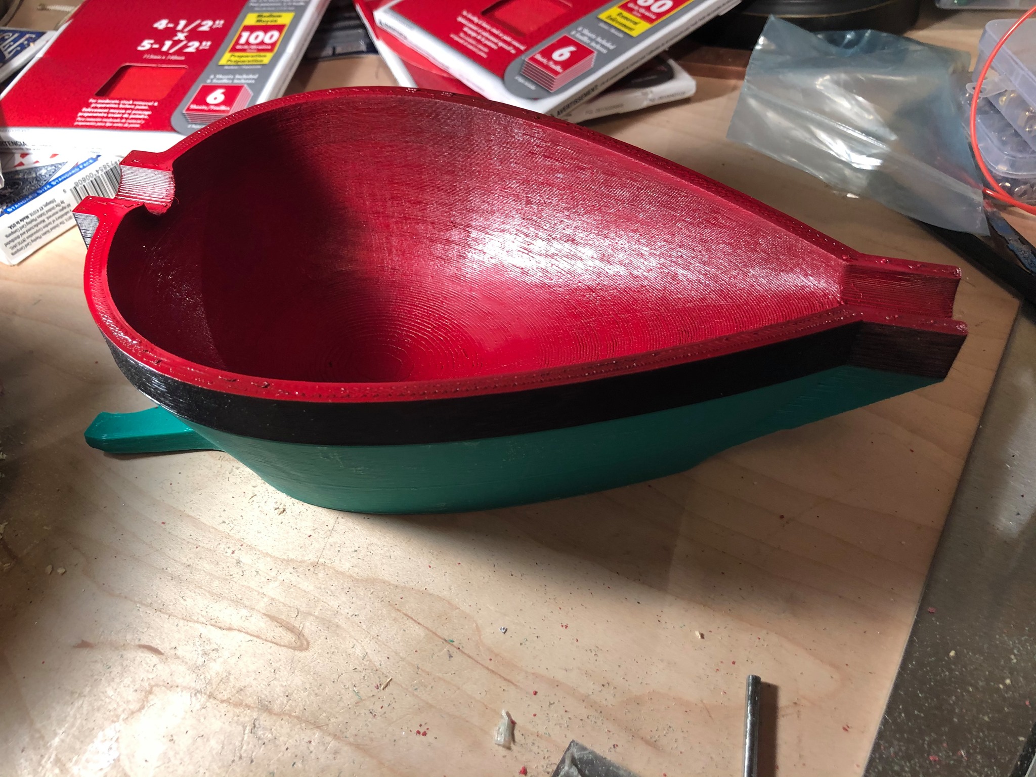
The nacelle mold was 3d printed in about 8 hours on my Prusa I3 mk3 with an 0.6mm nozzleThe mold after sanding, filling with sanding primer, sanding again, and lastly waxing
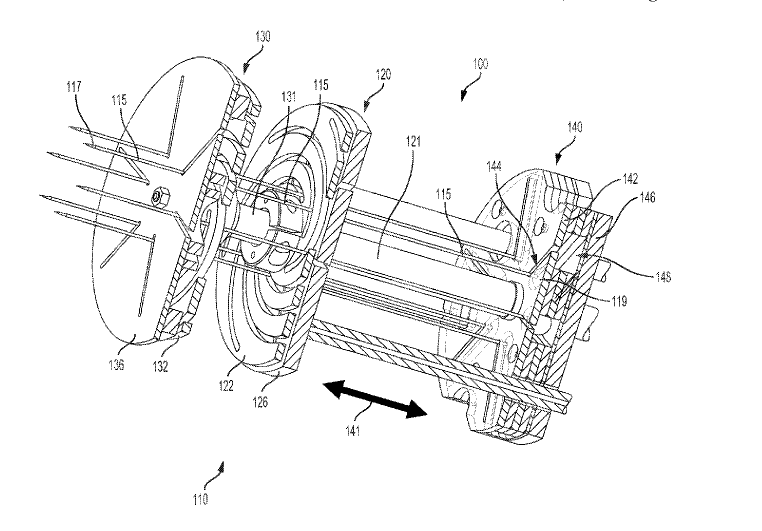
Overview drawing of the Kirkwoood Conical Iris Gripper
I was issued US Patent number 10,710,247 on July 14th 2020 for a new type of robotic gripper device uniquely able to grasp difficult-to-grasp food items.
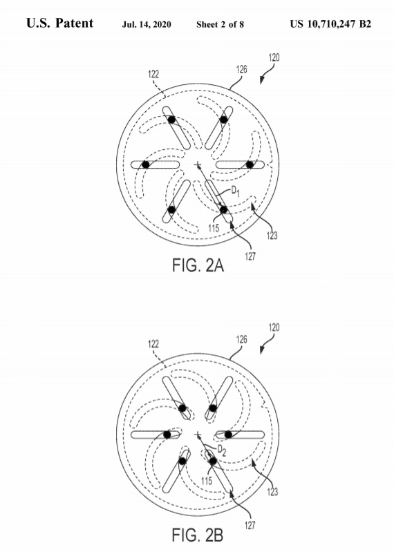
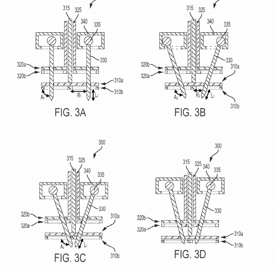
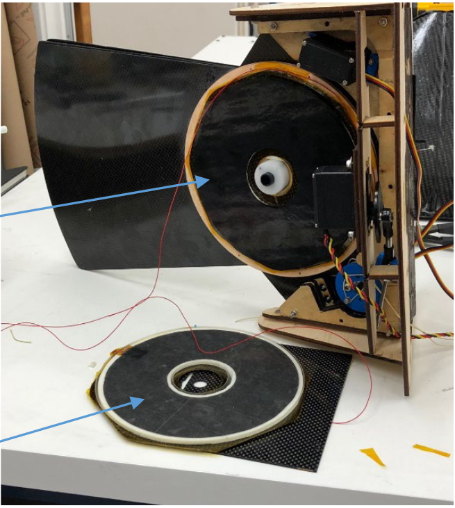
Robotic preparation of food is hard, in part, because of the difficulty of grasping and manipulating irregular shaped, slippery, and loose aggregated cooking ingredients like chopped onions, shrimp, or loose lettuce. I was asked to consider if any new design could meet the needs of this task, and prototype it. From my previous work with mechanical iris development inspired by the international space station’s Canadarm gripper, (see: CNC Bubble Iris), I realized that a novel 3-degree-of-freedom gripper could meet this need: a conical cage of slender spears, which could change shape in three different ways: taper angle, diameter, and extension. With these motions, I realized it was possible to make a highly effective gripper with a wide repertoire of potential grasping strategies, which could allow for a huge range of ingredients to be handled by a single gripper. The gripper can either open or close like a hand gathering and grabbing a handful of food, or stab like a fork, push food off of that fork, or dispense loose food items gradually, e.g. ‘sprinkling’. This gripper went on to become the primary end effector for a $1M+ commercial research project
The conical iris gripper was rapid prototyped with 3d printing, laser cutting, OEM parts, and a minimum of machining, over the span of about two weeks with other projects going on. The initial prototype was made using mostly laser cut acrylic and off the shelf parts, with a materials cost of less than $150.
I’m pleased to release a new publication in the Twenty-Second International Conference on Composite Materials (ICCM22) entitled “Enabling Biomimetic Morphing UAVs” with colleagues at SRI, the University of Southern California, and NextGen Aeronautics.
This publication details one application of a technology I have helped develop with my colleague Roy Kornbluh at SRI: ultra-lightweight, ultra-low power, electrolaminate clutches and mechanical multiplexers for reconfigurable systems in aerospace, astronautical, and terrestrial robotic applications.
My role in this project was to mechanically design a demonstrator tailfin assembly using these new lightweight, low power, electrolaminate clutches to lock control surfaces of aerial vehicles into variable area configurations. I did all the mechanical and electrical design as well as composite fabrication of the carbon fiber tail and rear fuselage assembly.
Internal structure of prototype electrolaminate clutched tailfin assembly that I designed and built.Molded carbon fiber tail assembly that I designed and built for the Air Force Office of Special Research as a demonstrator of new application of lightweight, low power, electrolaminate technology.
Abstract: This paper reports on the design and testing of a practical, morphing wing aircraft. We intentionally mix and match elements of avian inspired design with novel technologies and proven mechanical components to provide a demonstrator aircraft that shows, in the simplest way, what benefits accrue from basic morphing changes. The simplest and most beneficial morphing concept is to change the wing area and aspect ratio, and it is easy to show that, for an otherwise fixed example configuration, a factor of three decrease in wing planform area can sustain a predicted lift:drag ratio, L/D = 9, when the vehicle flight speed U doubles from 12 to 24 m/s. Without morphing, L/D would be 6.5. Such a large area change can be achieved with a telescoping wing, which is not biomimetic, but is practicable and achievable using standard and custom 3D printed components. We combine this variation with a tail-body configuration that is bio-inspired, and suggested by previous and continuing work on the vehicle-level flight efficiency of tailless aircraft, where a standard tail geometry is replaced by a trailing edge flap that converts the cargo-carrying body into a lifting body. The practical shape-changing is enabled by the use of novel electrolaminate materials that can quickly change stiffness at varying positions/postures.
A succinct summary of how learning to weld affects your ability to think outside the box. Forgive the language please, it spices the point.
I frequently describe learning to weld as one of the most empowering breakthroughs in my growth as a designer. All new fabrication skills open new opportunities to dream a little (or a lot) bigger, and welding suddenly let me see much more of the sorts of things around me as achievable by my own hand.
In general, I like to work on a principle that if I can find a way to enjoy the practice, the result will be both better and more authentic. (This is key not only to welding, but any skill). So I set out to find fun little excercises to practice welding on.
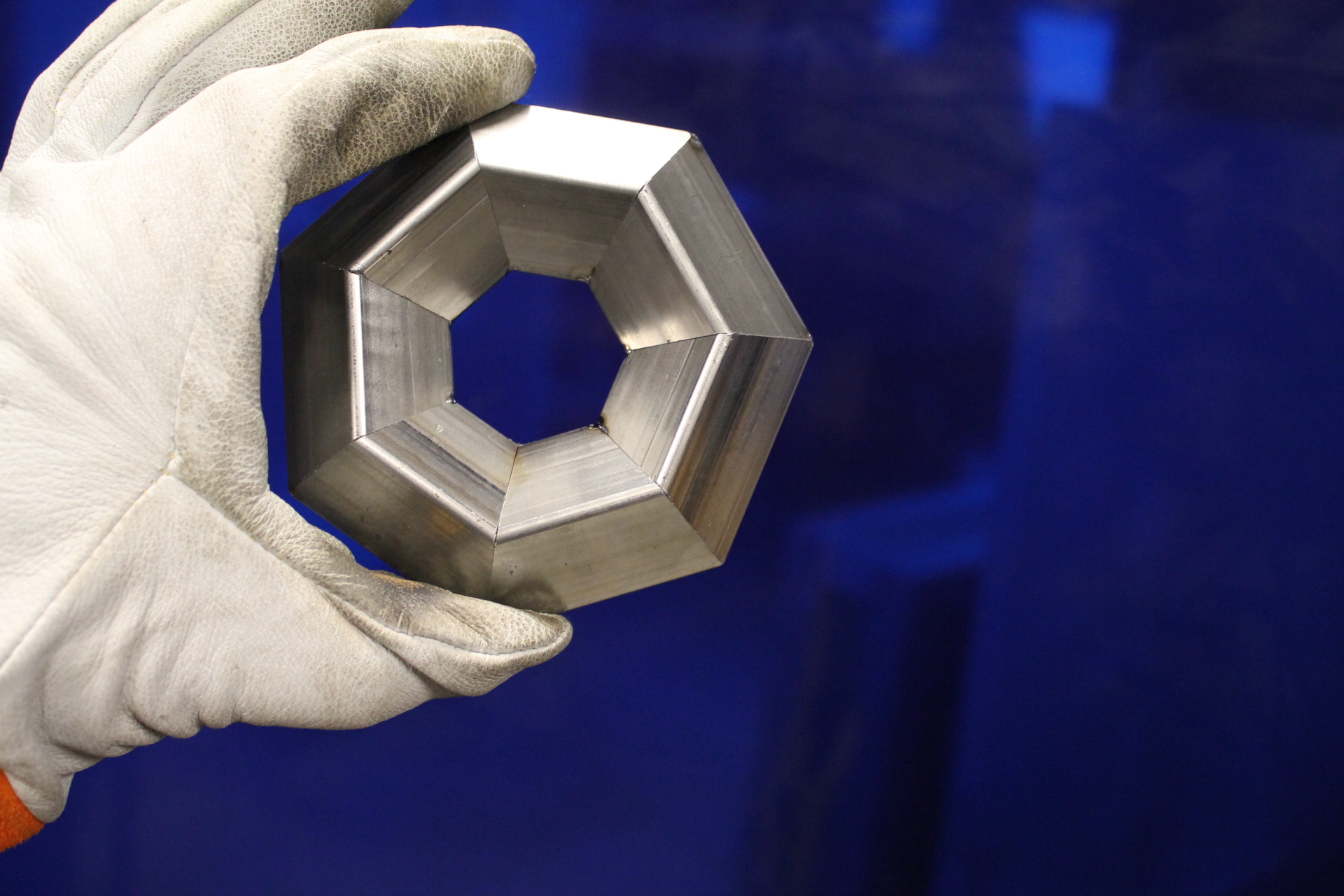
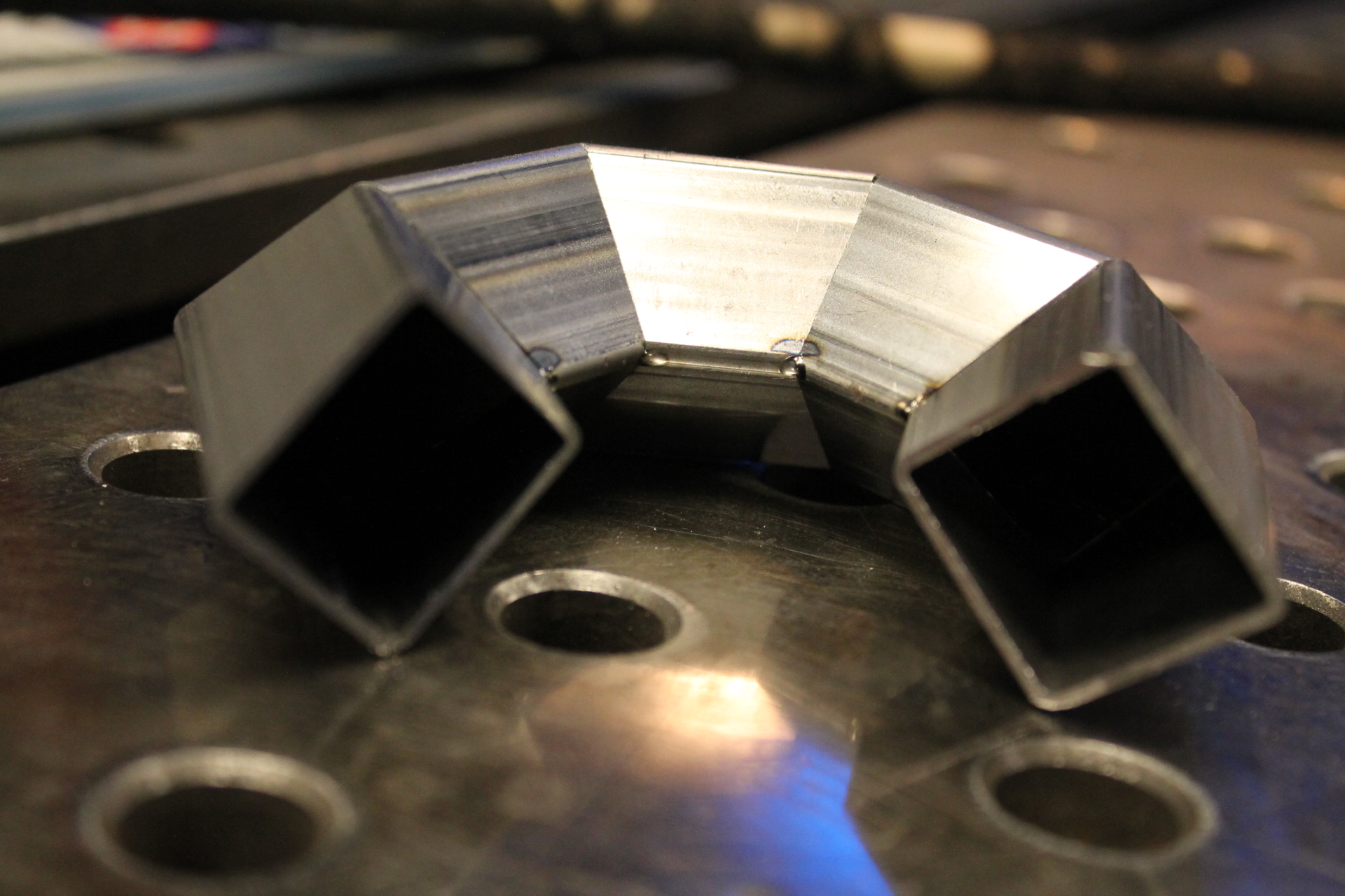
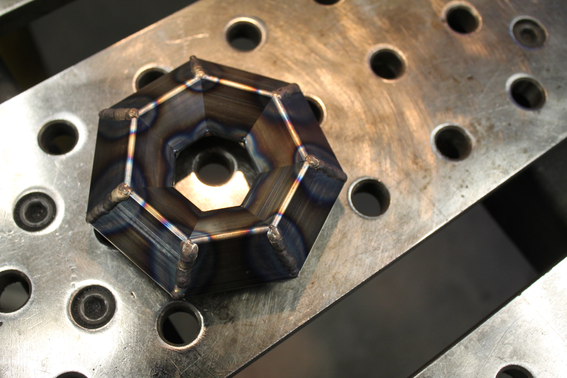
One of these excercises was making rings from square and round tubing. If you have a saw that can cut accurate angles repeatably, it’s easy to turn out a set of parts that will fit into a nice ring, with lots of seams to practice welding together. Below are the first such rings I undertook, when practicing TIG-brazing mild steel rings with silicon bronze filler metal. Along the way, I realized with delight that here was a great excuse to destructively test something, too. Thus, the video at the bottom, which shows one frame per hydraulic-pump-stroke, as I crushed the first ring and observed its failure modes.
Tacked at ID and OD. The fit of the bevel cuts is sublime! not a sheet of paper could be inserted at ID or OD of any joint. Spot on 64.3 degree (=90-(180/7)) bevel!
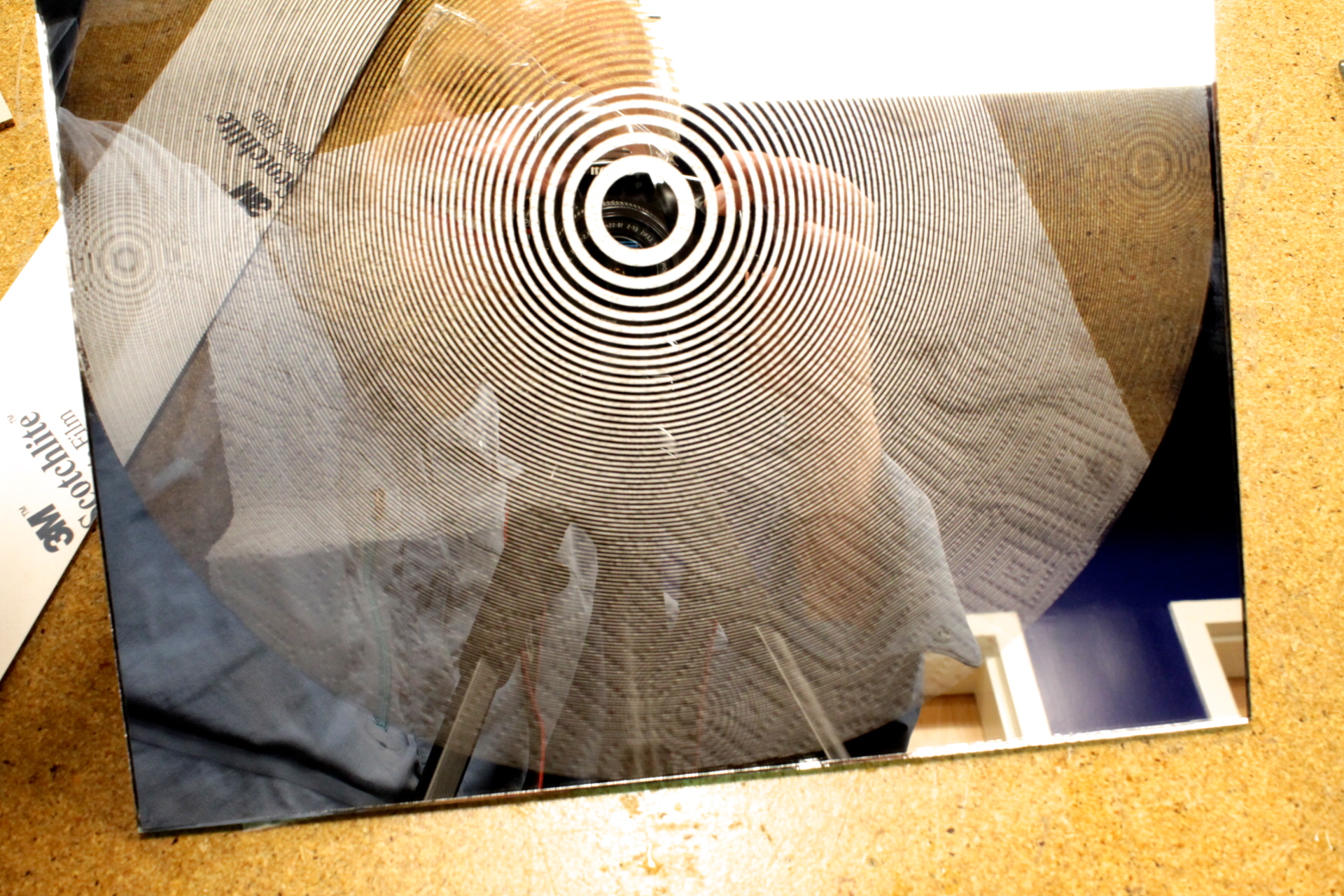
I’ve been playing with a new process in which I remove the silvering of mirrors in detailed patterns, leaving optically clear glass.
A zone plate made of mirror and optically clear glass zones will focus images in both reflectance and transmission. The focal length of this plate, at visible wavelengths, is too long to be practical though. I’m experimenting with shorter focal length, finer ring spacing, zone plates.
My first experiment was to make a Zone Plate, but my current process didn’t have enough resolution to make fine enough lines for a zone plate of short focal length at normal visible wavelengths around 600nm:
However, the process is fantastic for barrier grid a.k.a. moiré a.k.a. ‘strip’ animations, and for an afternoon project this has borne incredible fruit: only about a dozen promising directions to go from here! I decided to focus first on making an animated cautionary text and moving image safety sign for vehicles, especially bicycles, especially helpful for night-time visibility.
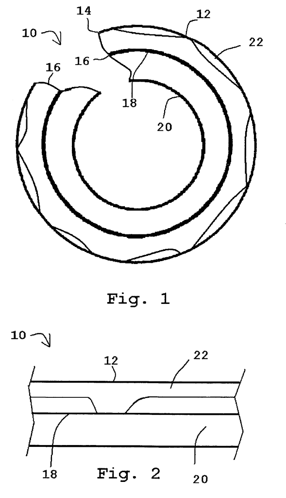
Grey Iron and Ductile Iron Pipe are the dominant conveyances of water and sewage in American infrastructure. These types of iron have carbon and iron constituents whose relative distribution and crystal sizes determine their mechanical properties. Over time, this material are susceptible to ‘graphitization corrosion’ in which either graphite particles migrate and aggregate (typically at temperatures above 800F) or in which local electrochemical corrosion at room temperature results in preferential loss of the iron / ferrite constituent of the matrix. When this happens, the pipe becomes brittle, and mechanical insults like vibration or thermal stresses can exceed the flexibility of this now brittle material, leading to brittle failure and cracks. However, this corrosion can be invisible, because the remainder graphite particles are cohesive and the pipe appears physically unchanged.
Illustration from the patent, indicating changing composition of portions of a grey iron pipe wall, in cross section.
During road work, construction, and maintenance operations, these pipes are visually inspected, but because pipes experiencing graphitization corrosion often look physically unchanged – the graphite material remains in the same contour as the original material, a method of detecting the change in properties of the pipe was needed which did not depend on visual changes, or subjective “bang on it with a hammer” subjective methodology, as was the state of the art previously. We needed a non-destructive method of detecting the changing properties of the pipe.
The insight of this patent is that the changing microstructure of the graphitized material has reduced magnetic properties due to the loss of iron. This could be sensed by measuring the magnetic permeability of the pipe, or it’s consequential magnetic measurements like inductance or the force developed within a fixed magnetic field. At the urging of my mentor Dr. Mehrooz Zamanzadeh, President and Principal Scientist of Matco Services, and with my assistant Sam, I developed a prototype sensor and confirmed that magnetic flux concentration, magnetic force, and inductance measurements are all viable methods of non-destructive detection of changed microstructure and ferrite loss in grey iron and ductile iron pipe. US Patent 8154279 was issued on April 10th 2012 for “Non-destructive testing apparatus for the detection of graphitization of iron”

